Cademix Institute of Technology, Vienna, Austria | +43 650 967 7080 | info@cademix.org

Estimated Reading Time: 6 minutes
Sanju Cherian From CAD to FEA

How to become a FEA Simulation Engineer from a CAD Design Engineer

By Sanju Cherian

 The industry requires Finite Element Analysis Experts more than ever. This article compares the skills sets and describes the pathway how to become a FEA Simulation from a CAD Design Engineer. It is the powerful approach to perform What-if experiments.

INTRODUCTION

 The industry requires Finite Element Analysis Experts more than ever. This article compared the skills sets and describes the pathway how to become a FEA Simulation from a CAD Design Engineer. 

Finite Element Analysis (FEA) is a computer-aided engineering (CAE) tool used to analyze how a design reacts under real-world conditions. It is also known as a very powerful approach to perform What-if experiments. Useful in structural, vibration, and thermal analysis, FEA has been widely implemented by automotive companies. It’s used by design engineers as a design tool during the product development process because it allows them to analyse their own designs while they are still in the form of easily modifiable CAD models, providing quick turnaround times and ensuring prompt implementation of analysis results in the design process. While FEA software is readily available, successful use of FEA as a design tool still requires an understanding of FEA basics, familiarity with the FEA process and commonly used modeling techniques, and an appreciation of inherent errors and their effect on the quality of results. When used properly, the FEA becomes a tremendous productivity tool, helping design engineers reduce product development time and cost.


Computer Aided Design (CAD) is an important skill in today’s world. It has many real world applications, from building cars to modelling construction sites. CAD is a high-earning career path with attractive remuneration whilst offering the chance of artistic expression. A good CAD designer is continuously learning and improving their skills and will always find ways to challenge themselves. A CAD system plays a major role in how products are designed. How well you are able to manage and implement your own CAD system has a large impact on your company’s overall productivity and success.

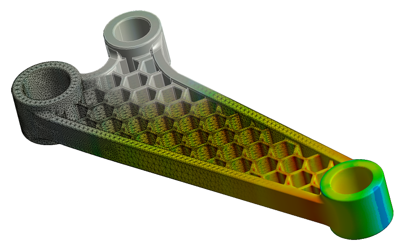
Finite Element Analysis Honeycomb lightweight

PRINCIPLES OF FEA

Finite Element method is generally used in FEA to compute approximate solutions of boundary problems (field problems) in engineering. “Field variables” are the variables of interest that are governed by a differential equation. They must achieve a boundary condition for specific values of the variables (or related variables). A “node” is a specific point on the finite element that contains the value of the field variable — that is normally explicitly calculated. These values are then used to compute values at non-nodal points through interpolation of values at the nodes using shape functions.


APPLICATION OF FEA IN CAD

FEA is among the most powerful and commonly used features in CAD design.

It is integral to CAD for analyzing an object through the use of finite elements that include small rectangular and triangular shapes. To analyze the whole object, each finite element in the whole object network is analyzed, and the outcomes are combined to plot the overall behavior of a complex object. Each element can be analyzed for certain property thresholds like stress-strain, dynamics, thermal properties — or any other characteristics (depending on where it is applied).

In a CAD workflow, you can define each element and network structure as you require in your design.

Key features of a good FEA Simulation Engineer and a CAD Design Engineer

CONCLUSION

FEA allows engineers to conduct the simulation of a designed model rather than having to create a physical model for testing purposes. FEM during analysis allows modeling of a diverse number of material types, and the ability to monitor how confined effects impact a small area of design in complicated geometry. Fluid dynamics, deformation of a vehicle from collision and stress on human bones are some of the practical utilization of finite element modeling software by engineers. A CAD Engineer learning these key attributes will make them a successful FEM Simulation Engineer having the skills of both Design and Simulation helping organisations to create better and sustainable products.


References

  • Developing Expert CAD Systems by V. Begg
  • Finite Element Analysis (FEA) for Design Engineers by Dr. Paul Kurowski
  • Sub-modeling finite element analysis of 3D printed structures
    J Zarbakhsh, et. al. Multi-Physics Simulation IEEE 2015

Related Topics

People also visited:

Shopping Basket