Painter-bot is a robot that makes painting with the help of a computer aided software and computer numerical control system (CNC). In Cademix Acceleration program Mechanical and Electrical engineers decided to create a Painter-bot. In this article we will explain how to make a simple painter-bot to use it for desktop use.
Author Identification Codes: CX2958176043 and CX7184059623, Cademix Institute of Technology.
Introduction
Nowadays, using Robots instead of human are becoming a very common topic in each industry. Industrial paint robots have been used for decades in automotive paint applications. These robots are still in use today but are of inferior quality and safety in comparison with new devices. The newest robots are accurate and deliver results with uniform film builds and exact thicknesses. The modern paint robot varies much more in size and duty to allow many configurations for painting items of all sizes. Painting robots or painter-bots for short generally have five or six axis motion, three for the base motions and up to three for applicator. In this article we will discuss how to create a new simple painter-bot from used CD-ROMs and Arduino boards. Then we will make a robotic paint of Cademix institute Logo.
Mechanical parts-CD/DVD-ROMs
There so many steps should be done to create a paint by a painter-bot. At first, we try to define the concept of making Painter-bot. If our device wants to paint any object, it must move along X-Y coordination. To move the device in vertical and horizontal paths, we need a stepper motor movable platform. They are all in old and second-hand CD/DVD ROMs. We will need two CD/DVD ROMs for this project.
Stepper motor
Stepper motors are DC motors that move in discrete steps. They have multiple coils that are organized in groups called “phases”. By energizing each phase in sequence, the motor will rotate, one step at a time. With a computer controlled stepping you can achieve very precise positioning and/or speed control. For this reason, stepper motors are the motor of choice for many precision motion control applications.
Axis
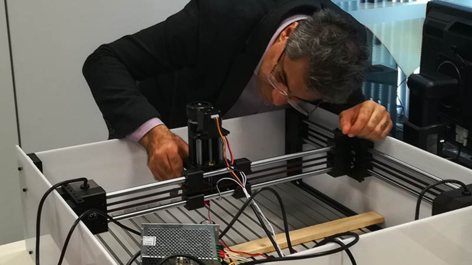
Stepper motors are used from old CD-ROMs. Two stepper motors and a platform are brought out from the CD-ROMs. We will need something to attach it on X axis, a flat surface. On that surface we will attach the servo motor (Z axis) and the pen base. Pen (or pencil) must be able to move up and down with the help of servo motor. Servomotors can control angular or linear position, velocity, and acceleration. Next, we need to attach a wooden (or plastic) surface to the Y-axis. Place a piece of paper on top of it to print text and images. Now that we are ready to start, we will build the circuit and test the stepper motors (X-axis and Y-axis). When we look at the picture above on the breadboard schematic. Wiring the stepper motor requires patience.
What are the Electrical parts?
Electrical parts are playing the main role to create a painter-bot. In this section, we are trying to describe these parts in simple words.
Stepper motor controller or driver
The overall performance of a stepper motor depends heavily on the drive circuit. Torque curves can be increased to greater speeds if the stator poles are reversed faster.
Arduino Uno board
Arduino UNO is a low-cost, flexible, and easy-to-use programmable open-source micro-controller board that can be integrated into a variety of electronic projects. This board can be interfaced with other Arduino boards, Arduino shields, Raspberry Pi boards and can control relays, LED s, servos, and motors as an output.
External power supply instead of USB cable
Although USB used to connect, communicate, and power supply between computers and electronic devices, in this project we use External power supply to move Stepper Motors.
Let’s get to work
After assembling the Electrical and mechanical devices on the platforms, we should start soft-ware issues to move to simulation step. There are 2 fundamental steps to reach the simulation.
1) We have to create G-code file in interface software from the sketch
2) Upload G-Code in painter-bot to create picture
1) Creating G-code
G-code is a language that humans use to tell a machine how to do something. g-code contains commands to move parts within the printer. G-code consists of G- and M-commands that have an assigned movement or action. All CAD/CAM soft-wares such as Solid works, Catia, Matlab, etc. can create G-code from each graphic file. After installing the G-code simulator, we go to create G-code from a picture. When we upload the picture we should export it as G-code file. In a typical application, a compiler or assembler converts a program’s source code (such as in C or assembly language) to machine code and outputs it into a G-CODE file. The G-CODE file is then imported by a programmer to “burn” the machine code into a ROM, or is transferred to the target system for loading and execution.
2) Uploading G-code file for profile drawing
By using interface software, we can export G-Code to the painter-bot hard-ware to plot the picture. Press the “Run on Arduino” button and program your board from your browser!


